ESD Thermoformed Tray Manufacturers: 2026 Supplier Guide
Compare ESD thermoformed tray manufacturers by material construction, finished-part evidence and the handling route, including automation and reusable trays.
Utz's thermoformed component holders serve storage, transport and automation applications, with conductive constructions available. Its wider container range makes it relevant when the tray must fit an established tote or conveyor system. The holder, surrounding frame and outer container need defined interfaces and a clear supply boundary. A system-level drawing can show how the stack is supported and located, while the quotation identifies which elements and qualification activities the supplier will provide.
Scafa's ESD tray portfolio includes several polymer options, including PS and ABS constructions. This gives buyers a starting point for matching electrical requirements with cavity geometry and reuse conditions. The material name and a published resistance range are screening information; the approved grade, forming conditions and test method still need to be identified for the project. A finished-tray report tied to a drawing revision is more useful for repeat purchasing than a general statement that a material is ESD suitable.
Conductive Containers describes engineering, tooling, forming and CNC trimming in its in-house thermoforming services, with conductive and dissipative material options. Trays, covers and clamshells can be considered together when a project requires several protective elements. The package proposal should identify the function of each component and the evidence associated with it. This is particularly useful for an existing tote: the buyer can evaluate the proposed insert and cover against a known outer-container interface.
Plastiform's electronics guidance explicitly connects ESD performance with forming depth and sheet stretching. It also discusses automated handling, cleanroom applications and cleaning. That makes it a relevant contact for trays whose deepest regions are important electrical or mechanical contact points. The drawing review should establish the locations that govern acceptance and the evidence needed after forming. A material recommendation can then be assessed in the context of the actual cavity rather than a flat sheet alone.
ORBIS offers custom thermoformed packaging within its reusable packaging portfolio. Its published battery-sector offering also identifies ESD trays and conductive or dissipative materials. It is relevant when the purchase includes a return loop between plants. The logistics brief should describe handling, outer containers, return collection and tray identification. Those operating requirements sit alongside the electrical specification and determine how many trays the system needs in circulation.
Groupe CTCI's electronics tray applications include boards, connectors and sensors. These components have different support and access requirements, even when their outside dimensions seem similar. A useful development brief includes dimensional variation, fragile areas and the intended pickup method. The proposed cavity can then be evaluated with representative parts at the loading station. Mechanical acceptance and electrical acceptance should remain identifiable in the approval record, so a successful handling trial does not silently become approval of every protective property.
KONI lists made-to-order transport and ESD trays in its production portfolio, alongside CNC toolmaking and industrial equipment capabilities. Its thermoforming service provides a route for discussing custom tray geometry. The production station is a useful starting point: orientation, locating surfaces and empty-tray movement all affect the design. A project-specific proposal should identify the electrical material construction and inspection scope as well as the tool. These details make the offered tray comparable with other suppliers' responses.
Ready-Made offers stock and custom layouts, with a material portfolio that distinguishes conventional plastics from conductive and antistatic versions. A stock compartment pattern may avoid a dedicated tool, provided the required material is available in that format. The evaluation still needs component contact, contamination and electrical criteria. A part fitting into a stock cavity establishes only geometric compatibility; the material version and protective arrangement must be identified before it becomes an approved electronics-handling tray.
Sinclair & Rush's VisiPak business describes testing of incoming material and finished parts in its ESD tray offering. It lists conductive, dissipative and antistatic options, together with stacking and automated-handling features. For a pick-and-place application, the purchasing team needs to know which tests apply to the selected construction and which dimensions control equipment pickup. Electrical reports and cavity measurements should reference the same tray revision and material, keeping the two sides of qualification connected.
Thermoformed electronics trays provide shaped pockets, supports and stack features around a component. Their role can range from a carrier used only inside a controlled production area to an insert in a shipping package. The route determines what protection is required at each stage and which other packaging components are involved.
The EOS/ESD Association's packaging guidance distinguishes three functions. Low-charging behavior limits charge generation during contact and separation. Conductive or dissipative properties allow charge transfer under suitable grounding conditions. Discharge shielding protects the contents from an external discharge. A resistance result does not establish all three, and a conductive open tray does not by itself demonstrate the shielding performance of a closed package.
The same guidance describes low-charging, conductive or dissipative packaging inside an ESD protected area, with discharge shielding additionally required outside that area. The responsible ESD team translates this into the approved construction and test requirements. Labels such as antistatic or ESD-safe need that context; color cannot establish the protection provided.
A route drawing can identify loading, inspection, storage, shipping and unpacking, including where covers are removed. It should include contract manufacturers and repair operations where applicable. The approved package may change at those handoffs. Documenting them prevents procurement from buying a tray for one controlled station and assuming it covers every subsequent journey.
ESD properties belong to the specified material construction. A proposal may use a filled polymer, an additive system or a surface treatment; each needs an identifiable grade and supplier specification. The base polymer also has to satisfy the tray's forming, impact, cleanliness and service requirements. An ABS or PET label alone does not describe the electrical behavior of the delivered article.
Plastiform notes that deep forming and substantial stretching can reduce ESD performance, depending on the starting material and its conductivity. The practical consequence is a finished-part test map. Flat flanges may be convenient to measure, but the areas that support or contact the component can be more relevant to the application.
A useful map identifies the drawing revision, test locations, measurement method and conditioning. Reports should state what was measured, the instrument setup and the agreed acceptance criteria. Surface resistance, volume resistance and resistance to a grounding point describe different measurement arrangements. A number without its method and units cannot serve as a reliable purchasing specification.
The ESD coordinator should select criteria appropriate to the product and the applicable program, including the standard edition used. A copied resistance range from another supplier's data sheet may refer to a different material, geometry or test environment. The enquiry should make any unresolved criteria visible before suppliers produce samples.
Reusable trays introduce additional process history. Cleaning, abrasion, contamination and storage conditions need to be included in the proposed use sequence. Evidence for a new tray does not establish an unlimited service life. The reuse plan should define the relevant inspections and the conditions under which trays are removed from circulation.
Material substitutions and changes to coatings or forming conditions should reach the technical owner before production. An unchanged color and cavity layout can conceal a changed construction. Batch identification and revision control make it possible to connect incoming inspection with the material and process that were originally approved.
Mechanical qualification begins at the component contact points. The drawing should mark acceptable supports, delicate leads, optical surfaces and prohibited contact areas. Component tolerances and variants matter as much as the nominal CAD outline. A tray that grips one sample securely may interfere with another acceptable version of the same component.
For automated handling, the equipment interface needs its own definition. Tray orientation, locating edges, pickup clearance and cavity position influence loading and removal. A representative fixture or the intended equipment can expose interference during a pilot. Partially loaded trays should also be considered if that state occurs in production.
Stacking loaded trays and nesting empty trays are separate conditions. A design review should establish how stack loads are carried and whether the component can touch the tray above it. Empty-tray separation and correct orientation affect line operation and return handling. These observations belong in the trial record alongside dimensional and electrical results.
The pilot should use the agreed construction and production-representative tooling. Any differences from the planned supply route need to be stated. It can then follow the real handoffs: loading, movement, storage, unloading and return. Operator observations often reveal awkward grip areas or ambiguous orientation that the cavity drawing did not resolve.
Cleanliness requirements need equally concrete language. If a product is sensitive to particles, surface contamination or cleaning residues, the buyer should identify the relevant restrictions and evaluation method. An ESD claim provides no general cleanliness approval. Electrical performance and contamination evidence should both relate to the construction actually supplied.
Final approval should retain the drawing, material specification, agreed test methods and representative sample reference. Open issues need an owner and a defined recheck after correction. That record gives receiving staff a usable baseline and allows a future supplier change to be evaluated against known requirements.

The purchase includes more than the tray when covers, outer containers or return logistics provide part of the approved protection. A common scope sheet should identify each component, the party supplying it and the associated evidence. Otherwise, two attractive unit prices can describe substantially different handling systems.
A focused RFQ includes:
Stock and custom trays can then be compared on the same functional basis. A stock format may reduce development cost while using more space or requiring a different handling method. A custom tool needs to justify its cost through the geometry, packing density or equipment compatibility the project actually requires. Minimum orders and delivery schedules should come from current quotations.
For returnable trays, the quantity in circulation depends on time spent in production, transport, receiving and return collection. Purchasing and logistics should model those stages using their own operating data. Delayed empty returns can increase the required tray population even when the production demand remains unchanged.
The agreement should also cover tool ownership, repairs and revision identification. A changed pocket or stack feature can make old and new trays incompatible in an automated process. A clear method for separating revisions reduces the chance of mixed batches reaching the line and makes replacement purchases easier to manage.
No. Antistatic commonly refers to low-charging behavior. Conductive or dissipative performance concerns charge transfer, while shielding concerns protection from external discharge. The specification should name the required functions and evidence for the actual package instead of treating those labels as interchangeable.
It supports material selection, but the tray has a forming history and geometry of its own. Deep pockets and contact regions may need finished-part measurements. Acceptance should connect incoming material controls with the agreed test locations and conditions on production trays.
Its role depends on the complete packaging system and the approved route. A material property does not establish the protection of an open arrangement. The ESD control principles explain the additional shielding role outside a protected area. The ESD team should define the cover, enclosure or other packaging for that journey.
There is no universal reuse count for all thermoformed ESD trays. Material, cleaning, wear and the handling route influence suitability. The approved return loop should specify inspection and retirement criteria, including what happens to damaged, contaminated or unidentified trays.
For delicate molded components, see micro injection molding companies. For final medical-device packaging, compare PETG medical tray manufacturers; a production ESD carrier and a medical packaging system require separate specifications.
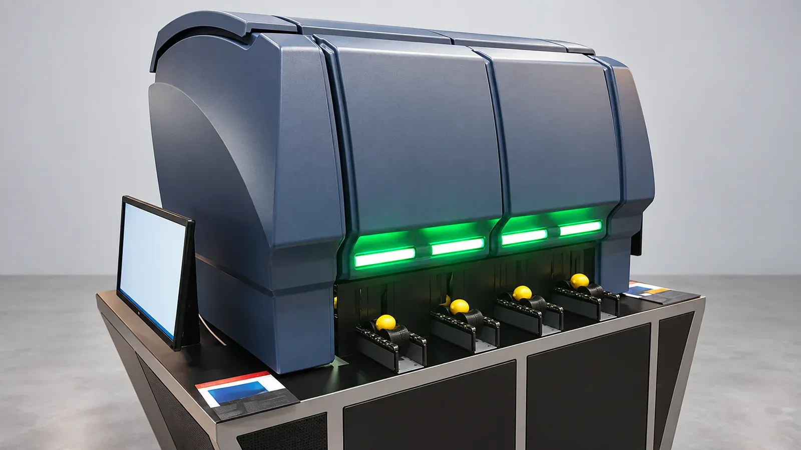
Photo: Scafa. Lighting and background adjusted; product geometry retained.
Choose a heavy gauge thermoforming machine around your parts, materials and output, with ten suppliers and guidance on heating, tooling and acceptance trials.
Read guide