See how mold orientation, draft, radii, vacuum, cooling and tolerances shape reliable thermoforming tools, part quality and production cost.
A thermoforming mould does more than reproduce a shape. It controls how the heated sheet stretches, where air escapes, how quickly the plastic cools, which surface receives the best definition, and whether the finished part can be released without distortion. A good product model can still perform poorly if the tool does not support the material and production method.
That is why thermoforming mold design should begin with the complete manufacturing route: forming method, sheet grade, starting thickness, annual volume, surface requirements, trimming, inspection, and expected tool life. Readers who need a broader process overview can first review What Is Thermoforming? Process, Types and Applications.
Join PlasticParts Hub
Create an account to connect with companies and send RFQs.
The same geometry may need a different mould for a prototype run, a cosmetic pressure-formed housing, or continuous high-volume packaging. Before modelling the tool, define:
vacuum forming, pressure forming, twin-sheet forming, or another method;
sheet-fed or roll-fed production;
material grade, colour, texture, and thickness;
expected quantity and cycle-time target;
visible and assembly surfaces;
critical dimensions and inspection method;
trimming and secondary operations;
tool life, maintenance, and likely future changes.
These decisions affect tool construction, cooling, vacuum layout, surface finish, and cost. Building a production tool before the process is stable often creates expensive corrections later.
Choose the correct mould orientation
A male mould projects into the sheet, while a female mould draws the sheet into a cavity. This choice determines where the tool-side surface appears, how the material distributes, and how the part releases.
Male tools can be useful when internal dimensions or the inside surface matter. However, the cooling sheet contracts around the tool, so adequate draft and reliable release are essential. Female tools often provide stronger definition on an exterior cosmetic face, but deep cavities can be harder to heat and vent evenly.
Identify which side must carry texture, logos, sealing features, or controlled dimensions. Changing mould orientation late can alter part size, draft direction, trim strategy, and wall-thickness distribution.
Select the tool material for its real production life
Prototype tools may be made from modelling board, resin, composites, or other easily worked materials. They can suit geometry trials and low quantities but may not provide the thermal stability, surface durability, or dimensional life needed for serial production.
Aluminium is widely used for production moulds because it can be machined accurately, repaired, textured, and fitted with cooling circuits. Cast aluminium may suit large forms or shapes that would be inefficient to machine from solid stock.
The cheapest tool is not always the lowest-cost production solution. Slow cooling, unstable dimensions, poor vacuum distribution, or frequent repairs can outweigh the initial saving.
Design draft for release
Draft allows a cooled part to move away from the mould. Near-vertical walls can grip the tool, especially on male forms where the plastic shrinks around the surface.
As an early reference, smooth female walls may begin around 1–3 degrees, while male walls often begin around 3–5 degrees. These are not universal specifications. Deep tools, textured surfaces, high-shrink materials, and long draw lengths may require more.
Draft must continue through pockets, ribs, lettering, and decorative transitions. Air-eject systems, removable inserts, split tools, or moving sections can solve difficult release conditions, but each adds cost and maintenance.
Use radii to manage material movement
The sheet must travel across every corner of the mould. Sharp transitions restrict that movement, concentrate thinning, and may cool the material before it reaches nearby detail.
Inside and outside radii should be considered with draw depth, sheet thickness, polymer, forming temperature, and surface expectations. As a preliminary check, an inside radius smaller than the starting sheet thickness deserves attention; two to three times the sheet thickness is often a more workable starting range. Deep geometry may need more.
A larger radius can improve material flow and repeatability but may change the product envelope. The final value should be agreed by the product engineer, toolmaker, and thermoformer rather than copied from a generic table.
Build vacuum and venting into the surface
Vacuum cannot form detail if trapped air has nowhere to escape. Holes or slots should be placed at the last areas expected to contact the mould: deep corners, narrow channels, lettering, texture, and enclosed features.
Hole diameter and spacing depend on material, finish, forming pressure, and tool construction. Oversized holes can leave visible marks; holes that are too small or too few can produce soft detail. The manifold behind the surface must also provide enough flow without dead zones.
Pressure forming needs especially consistent sealing and evacuation because surface definition depends on coordinated pressure above the sheet and vacuum below it. Vacuum forming uses lower forming force, but poor venting will still limit repeatability.
Plan heating and cooling with the mould
Tool temperature influences surface quality, shrinkage, release, cycle time, and distortion. A mould that removes heat unevenly can produce one stable region and another that remains soft after release.
Production tools may use water channels, cast-in tubing, temperature-control plates, fans, or other cooling systems. Thick tool sections, deep pockets, and isolated features often need special attention.
Maximum cooling is not always the goal. Cooling too quickly at the first contact point can freeze the sheet before it reaches nearby detail. The objective is controlled, repeatable heat transfer across the full cycle.
Decide whether plug assists belong in the tooling system
Deep draws and uneven geometry may need pre-stretching or plug assists to guide material before final vacuum or pressure is applied. Plug shape, material, temperature, speed, clearance, and timing affect wall-thickness distribution.
A plug should not simply copy the cavity at a smaller size. It must move material toward areas that would otherwise become too thin without marking or prematurely chilling the sheet.
Because the tool and plug work together, they should be developed as one forming system. Adding a plug late may change machine stroke, controls, heating, and mould layout.
Connect the mould to trimming and inspection
The mould establishes the formed geometry, but the final outline is often created by CNC routing, die cutting, punching, or another trimming process. Tool design should provide stable reference areas for trim fixtures and inspection.
Define where the part can be located repeatedly after forming. Broad datum pads, controlled flanges, or dedicated reference features are usually more reliable than flexible walls. Critical holes and mating edges should be dimensioned from datums that can be reproduced in both forming and trimming.
The trim line also affects clamping, seal area, scrap, nesting, and handling. It should be reviewed before the mould is released.
Apply tolerances to the right features
A thermoforming mould can be machined accurately, but tool accuracy alone does not guarantee identical part dimensions. Sheet thickness, temperature, stretching, shrinkage, cooling, release, and trimming all contribute to variation.
Tool-side dimensions are generally easier to control than free-side surfaces. Large flat regions may move after release. Material shrinkage may require tool compensation, but compensation should be based on trials, supplier data, and production experience rather than a universal percentage.
Separate requirements into tool-controlled surfaces, trimmed features, assembly interfaces, and cosmetic areas. Tight tolerances should be reserved for functions that justify additional process control and inspection.
Allow for maintenance and future changes
Production moulds need access for cleaning vacuum holes, repairing surfaces, checking seals, and maintaining cooling circuits. Components that wear or may change should be replaceable where practical.
Logos, date marks, local features, or product variants can sometimes be handled with removable inserts instead of rebuilding the whole tool. Documentation should record tool material, key dimensions, cooling and vacuum connections, surface finish, inserts, spare parts, and approved process settings.
Review the mould before manufacture
Before releasing tooling, confirm:
mould orientation and critical surface;
tool material and expected production life;
draft on every release path;
radii and likely wall-thickness distribution;
vacuum holes, manifolds, and sealing;
cooling and temperature control;
plug assists or pre-stretching;
trim line, datums, and fixture references;
tolerances and shrinkage assumptions;
maintenance access and replaceable details.
The sheet grade should already be defined. Thermoforming Materials: How to Choose the Right Plastic explains why polymer family, grade, texture, moisture, and thickness affect tooling decisions.
Treat mould design as process development
Successful thermoforming tooling is not created by offsetting a CAD surface and adding vacuum holes. It comes from coordinating the part, material, machine, forming method, cooling, release, and trimming.
A simple mould may be correct for a shallow functional cover. A pressure-forming tool with controlled temperature, dense venting, plug assistance, and replaceable inserts may be justified for a detailed visible housing. The right thermoforming mold design is the one that produces the required part repeatedly at an acceptable cycle time, cost, and maintenance level.
When the tooling requirements are clear, How to Find the Right Thermoforming Companies and Suppliers provides a practical framework for comparing forming, tooling, trimming, and production capabilities.
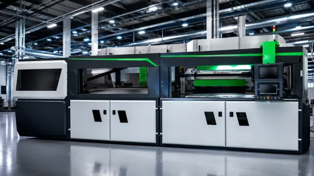
Tools Factory’s ENERGYLINE vacuum thermoforming series has been nominated for Poland’s “Teraz Polska” promotional emblem, highlighting its energy-saving dynamic heating system.