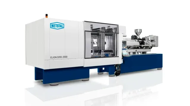
Image source: FANUC Europe. Official ROBOSHOT S180C SC Series image used as a suitable illustration; it is not presented as a photograph of the complete Fakuma 2026 production cell.
FANUC's Fakuma 2026 announcement contains the usual language about smart factories, artificial intelligence and connected production. For injection moulders, the more useful part is much more concrete.
The company will run two new all-electric ROBOSHOT applications at the October show in Friedrichshafen. One puts pressure sensors into every cavity of a technical moulding tool. The other links a larger machine directly to part handling and packaging for a medical application.
The first cell is built around the ROBOSHOT S180C and combines cavity-pressure monitoring on every cavity with simulation-supported hot-runner balancing. The second uses the ROBOSHOT S350C for automated medical packaging, with moulding, part removal and packaging presented as one compact production cell.
Neither idea is new in isolation. Cavity pressure has been measured for decades, and moulding machines have been connected to robots for just as long. What makes the FANUC display relevant is the way those tools are moving from specialist add-ons toward the normal architecture of an injection-moulding cell.
Cavity pressure answers a question the machine cannot answer alone
Injection moulders can collect a great deal of information from the machine: screw position, injection velocity, hydraulic or servo load, nozzle pressure, switchover position and cushion, among many other variables.
Those signals describe what the machine is doing. They do not always describe what the polymer is doing inside an individual cavity.
The gap shows up quickly in a multi-cavity mould. Every cavity is connected to the same injection unit, yet small differences in runner length, gate condition, venting, temperature or local tool deflection can change how each cavity fills and packs. A machine-side pressure trace may look repeatable while one cavity is gradually moving toward a short shot or another is being over-packed.
Pressure sensors inside the mould move the measurement closer to the part itself. Depending on sensor location, the trace can show when the melt arrives, how rapidly cavity pressure develops, what happens around the velocity-to-pressure transfer point and how pressure decays during cooling.
Monitoring every cavity, rather than adding one reference sensor, lets the processor compare cavities directly instead of assuming that a stable machine trace means a balanced mould.
Monitoring is not the same as automatic correction
It is easy to overstate what cavity-pressure data can do.
FANUC says the S180C cell will use cavity-pressure monitoring together with simulation-supported hot-runner balancing. The company says the combination can improve process stability, quality and waste reduction. It does not say that the system autonomously corrects every cavity in real time without engineering input.
The difference is important in practice. A pressure trace can tell an engineer that cavities are behaving differently. Simulation can help explain how runner geometry, valve timing or flow resistance may be contributing. The hot-runner system can then be adjusted or balanced according to the design of the tool and control package.
But the data still has to be interpreted correctly. A late pressure rise could be caused by runner imbalance, a cold gate, local venting, a damaged cavity, a material change or a combination of factors. Changing a valve-gate setting because the curve looks different is useful only if the root cause is understood.
For a production plant, the real value is therefore not a promise of a self-correcting mould. It is better visibility into a process that is normally hidden once the mould closes.
A useful tool for defining the process window
Cavity-pressure data becomes particularly valuable during mould qualification.
A conventional setup may be accepted after dimensional checks and a short capability run. With cavity traces available, the team can also see whether the acceptable parts are being produced near the centre of the process window or close to a boundary.
That can change how a process is documented.
Instead of recording only machine settings, a moulder can establish reference behaviour inside the tool. If the process later drifts, the technician has another point of comparison. The question is no longer simply whether injection pressure changed, but whether the pressure history experienced by the part changed.
This can be helpful for technical components where small variations in packing affect dimensions, sink, warpage or functional fit. It is also useful when a mould contains many cavities and quality teams need to know whether rejects are random or cavity-specific.
The limitation is data volume. Monitoring every cavity creates a large amount of information very quickly. Unless the plant defines which features of the pressure curve matter, operators can end up with attractive graphs that do not improve decisions.
A practical system should therefore reduce the traces to a small number of meaningful limits: melt-arrival time, peak pressure, pressure integral, transfer behaviour or another application-specific characteristic.
The S180C is part of FANUC's larger SC Series update
The S180C is one of the new machines in FANUC's ROBOSHOT SC Series. The platform was introduced with a larger mould envelope, faster clamping motion and more flexibility in injection-unit combinations while keeping the compact layout associated with ROBOSHOT.
FANUC lists the S180C at 180 tonnes of clamping force with 560 × 560 mm tie-bar spacing. Available screw diameters extend across a broad range, allowing the same clamp platform to cover different shot sizes and materials.
Those specifications matter to the Fakuma application because sensor-rich technical moulds and more elaborate hot-runner systems tend to consume space. A compact machine is only useful if the mould can actually fit between the tie bars and the cell still leaves reasonable access for maintenance, cables and water connections.
The SC Series also reflects a wider trend among electric-machine builders: improving productivity is no longer only about faster screw acceleration. Clamp motion, ejector timing, mould dimensions, process monitoring and energy management all have to be considered together.
The S350C cell moves the discussion downstream
The second Fakuma application uses the larger ROBOSHOT S350C in a medical-packaging cell. FANUC says the demonstration combines high-precision moulding with automated part handling and packaging.
The word "packaging" is important here because a moulding cycle is not complete when the mould opens.
In many medical and healthcare applications, the finished component has to be removed without damage, kept under controlled handling conditions, inspected or counted and transferred into a defined package. If those downstream operations are slower or less reliable than the moulding machine, improving the injection cycle does little for total output.
Integrating handling and packaging into the cell can reduce transfer steps and make the production rhythm easier to control. It can also reduce direct manual contact with parts, which may be useful for products with strict cleanliness or handling requirements.
FANUC has not stated a cleanroom classification or a specific regulatory validation for the Fakuma cell, so those should not be inferred from the phrase "medical packaging". A production system intended for a regulated medical programme would still need to be qualified for the actual product, environment and quality system.
The trade-fair cell is better viewed as an automation architecture: mould, machine, handling and packaging designed to operate as one process rather than as separate pieces of equipment.
Floor space becomes part of the automation calculation
FANUC specifically highlights the compact footprint of the S350C application.
Floor space is easy to ignore in an automation announcement. A robot can reduce labour and still produce a poor business case if the cell consumes valuable production area, complicates material flow or blocks maintenance access.
Medical and technical moulders often operate in buildings where clean manufacturing space is expensive. In those plants, output per square metre can be almost as important as output per machine hour.
A well-designed integrated cell can shorten the distance between moulding, inspection and packing. A badly designed one can create the opposite result: long robot travel, unnecessary guarding, difficult access and a downstream station that dictates the entire cycle.
At Fakuma, the useful detail to watch will be the actual movement of parts through the S350C cell. How far does the handling system travel? Where are rejects diverted? Can packaging materials be replenished without stopping the machine? How much access remains around the mould and robot?
Those questions tell more about production readiness than a headline cycle time.
Connectivity matters when it connects useful data
FANUC will also dedicate part of its stand to digital manufacturing. The company plans to show LINKi2, MES connectivity, EUROMAP 82.1 and 82.2 interfaces, WebAPI applications and Moldex3D integration, along with AI-based digital tools.
For an injection moulder, the value of those interfaces depends on what information actually moves through them.
A production system becomes more useful when cavity or machine data can be associated with a specific cycle, quality result and downstream disposition. If a vision system rejects a part, for example, engineers should ideally be able to trace that reject back to the relevant machine and mould data rather than investigating two separate histories.
The same applies to maintenance. A recurring quality shift may only make sense when viewed beside changes in mould temperature, hot-runner behaviour, robot timing or machine condition.
Connectivity therefore has practical value when it removes the boundaries between those records. Simply putting several dashboards on the same network does not achieve the same thing.
AI is present, but it is not the main injection-moulding story
FANUC's stand will also include generative-AI-supported voice programming for a CRX collaborative robot and other AI-based digital tools.
That is likely to attract attention at the exhibition, but it should not obscure the more immediate process-engineering developments in the moulding cells.
For most processors, cavity-pressure monitoring, faster fault diagnosis, repeatable part handling and better production data are easier to evaluate than a broad claim about artificial intelligence. They can be compared against scrap rate, setup time, labour content and process capability.
AI may eventually make those data streams easier to interpret. The underlying measurements still need to be reliable first.
The S180C demonstration illustrates the point well. Before software can make a useful recommendation about a multi-cavity process, it needs trustworthy information about what is happening in the cavities. Sensors and process discipline come before the algorithm.
What processors should examine at Fakuma
Visitors looking at the two ROBOSHOT cells should go beyond the normal questions about clamp force and cycle time.
For the S180C application, useful questions include:
where the pressure sensors are positioned in each cavity;
which pressure features are monitored for acceptance or warning limits;
how the hot-runner balancing is performed after the pressure differences are identified;
whether the system can distinguish a cavity-specific problem from a general material or machine change;
how reference pressure curves are stored after mould qualification;
how much additional mould wiring, maintenance and sensor calibration are required.
For the S350C cell, the focus shifts downstream:
how parts are transferred from the mould to packaging;
what happens when one station stops;
how rejects are separated and documented;
whether the automation can change over between products without extensive manual adjustment;
how cycle records are linked to handling and packaging data;
how operators access the mould, robot and packing equipment for routine maintenance.
Those are the details that determine whether an exhibition concept survives contact with a production floor.
The practical direction is more important than the "smart factory" label
FANUC is presenting the Fakuma stand under a broad digital-manufacturing message, but the two ROBOSHOT cells point to a simpler direction for injection moulding.
Measure the process closer to the part. Use those measurements to understand variation between cavities. Connect downstream handling to the moulding cycle instead of treating it as a separate operation. Make production data available outside the machine control when there is a clear reason to use it.
None of that requires a factory to hand decisions over to an opaque algorithm. It requires better information and tighter integration between equipment that already exists on the shop floor.
That is why the S180C and S350C demonstrations are worth watching at Fakuma. Their value will not be proved by how many digital features appear on the stand. It will be proved by whether the cells make difficult moulding and handling tasks easier to control, diagnose and repeat.
Editorial note: This article is an original Injection Moulding Hub analysis based on the sources above. It is not a translation or reproduction of FANUC's exhibition announcement.
Publishing note: The image is an official FANUC image of the ROBOSHOT S180C SC Series, used as a relevant illustration. Confirm external reuse rights with FANUC before publication on the public website.
Compare thermoforming and injection molding by part size, tooling, volume, materials, detail, tolerances, lead time, total costs, and production risk.